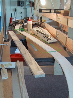
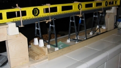
My model of the Coal Banks Bridge is over three feet long and I anticipated assembly and alignment of the spans and the towers was going to be tricky. I decided from the start to devise a way to build the bridge using a benchwork sub-assembly that allows the model to be built off layout and then dropped into place on the layout.
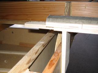
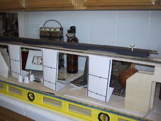
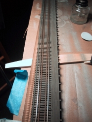
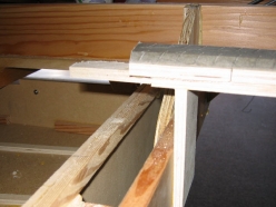
My approach was to construct roadbed where the bridge is to be placed as if there was not going to be a bridge. The assured the approaches to the bridge were aligned. I added extra risers to make sure the approach slope was held by the remaining roadbed when the span roadbed would be cut out. A frame was then constructed between both ends of the bridge. The bottom of the frame is constructed of 3/8″ birch plywood. More 3/8″ plywood was used to construct supports for the bridge abutments. These supports were also attached to the roadbed. I attached 1/4″ x 1″ wood strips to the edges of the bottom as temporary stiffeners while on the workbench.
When the frame was complete, tabs were glued where the roadbed was to be cut on the outside edges of the frame to be removed. Finally, a thin blade saw was used to cut the roadbed, stopping at the tabs. This allowed the bridge sub-benchwork to be removed from the layout as one solid piece.
Off bench, the roadbed was again cut to the proper opening for the bridge itself from this assembly. The abutments were then glued using epoxy to the frame risers.
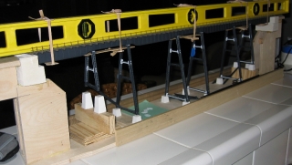
As the the bridge was undergoing final assembly, the offbench framework proved to be useful to align the towers and piers. Then entire assembly was dropped into place in the layout an screwed to the tabs.
Prologue
During the final assembly of the bridge into the layout, the stiffener strips were removed. This immediately introduced flexibility into the bridge frame that resulted in damage to the model. The only reason I had to settle on such a flimsy framework was because of the overall benchwork thickness restrictions. In a normal benchwork situation, the framework idea would be great, just make sure you build it to be stiff all the way through and after installation.
Coal Banks Bridge Project
This is the second in a series on my model of the Coal Banks trestle. Below is a listing of all the installments:
- Coal Banks Trestle: Decks & Railings (January 3, 2010)
- Coal Banks Trestle: Girder Spans (January 3, 2010)
- Coal Banks Trestle: Benchwork (January 2, 2010)
- Coal Banks Trestle: GN Design Practices (December 26, 2009)
- Coal Banks Trestle: Introduction (December 25, 2009)
Next: Girder Spans
