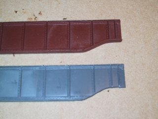
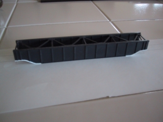
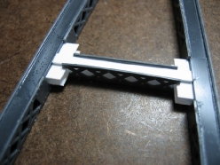
A key characteristic of GN Bridges is the tapering of the span girder height to match the tower span. The stock MicroEngineering spans are straight and needed modification to achieve the GN style. This modification had to be repeated twelve times over so my answer is to build a jig. I am a big fan of jigs. A jig is something to help you do something the same way multiple times. Jigs can often improve precision and accuracy of a component. If I have to build something more than once, I will tend to build a jig.
Girder Tapering Jig
For this task I used a Dremel tool router table mil the shape. I used various photographs to estimate the dimension of the taper against the panels of the girder. Using 3rd Planit CAD package I design a shape that looked pretty close and formed a template out of .060″ styrene.
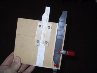
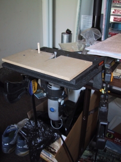
A piece of tempered board served as the basis for a jig to hold the pattern and raw girder firmly in alignment. I used a Dremel tool mounted in a routing table fixture to mill the raw ME girder to match the shape of the pattern. I obtained a Dremel router table accessory which allowed mounting the Dremel tool in a fixed and inverted position. Next I built the first half of the jig that would hold the pattern and raw ME girder in a fixed position. I built small clamps with screws to allow adjusting the pattern. Small pieces of stripwood held the raw gird aligned. Small spring clamps were used to hold the raw girder in place.
A second piece of hardboard was fitted with a peg that served to guide movement of the pattern while the raw girder would move past a cutting tool in the Dremmel. The other half the of jig is another piece of hardboard fitted with a peg. This piece is mounted on top of the Dremel table router platform using the bolts from the table router cards. A notch is cut out of the harboard to allow placement of the cutting tool. The jig that holds the pattern and raw girder is slid against the peg in the bottom half of the jig. This moves the raw girder against the cutting tool of the Dremel tool milling the GN taper in a controlled and repeatable fashion. Putting it all together, the hardboard piece with the pattern and raw girder is moved against the peg in the second half while the cutting tool mills the raw girder. This takes some trial an error to get the relative position of the pattern to match up with the position of the raw girder. You will need a few extra girder or cut blanks from more .040″ styrene. It took me about three tries to get it right which is not too bad.
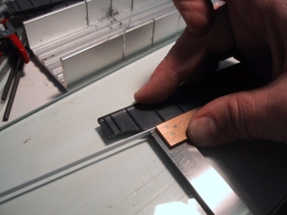
The milled surface of the girder will have a lot of crud from the milling as the tool cuts as much as it melts it’s way through the plastic. A little sanding cleans up the girders nicely. The milling removes a small amount of the girder webbing beyong the curve and into the straight portion to provide a good starting point to glue the replacement web. A small strip of styrene is added and with some patience and liquid styrene cement, the final girder end up looking like it was cast that way.
Span Assembly
One the girders reshaping is complete, the spans are assembled normally following the ME instructions. It is very important to have a good flat surface and weights to assure the spans are flat and true. I have a piece of 1/4″ plate glass that I find very handy along with a few pieces of steel for weights. When the assembly is glued and dry, I flip the spans and give them a few runs over sandpaper to help create a smooth flat surface that the track will later be glued to.
Coal Banks Bridge Project
This is the fifth article in a series on my model of the Coal Banks trestle. Below is a listing of all the installments:
- Coal Banks Trestle: Decks & Railings (January 3, 2010)
- Coal Banks Trestle: Girder Spans (January 3, 2010)
- Coal Banks Trestle: Benchwork (January 2, 2010)
- Coal Banks Trestle: GN Design Practices (December 26, 2009)
- Coal Banks Trestle: Introduction (December 25, 2009)
Next: Decks & Railings

