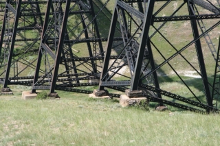
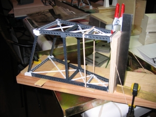
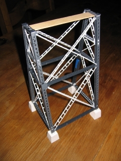
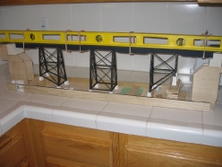
Construction of the towers presents a number of challenges to obtain the details we hilighted in the second installment of this nine part article. I started by determining what the profile of my Coal Banks coulee was going to be and the subsquent heights of the trestle bents. I wanted the bents to appear as if they were built around the terrain. Prototype towers had beams custom trimmed and angled and I wanted that same effect on my model. Drawing out the model to scale also helped me deal with fitting the model to slight 1% slope.
GN Sway Braces
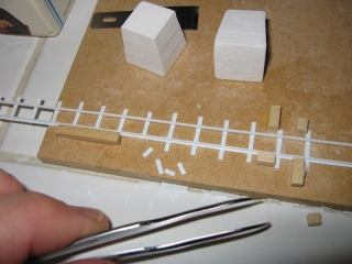
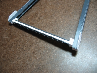
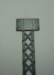
The sway braces on GN trestles were ladder like assemblies. The ME braces are a more traditional “X” pattern. In order to match the GN style, I had to build the braces from scratch styrene materials. There are a lot of these on my model so once again I had to devise a jig to assist. There are actually two widths to these braces as the opposing brace fits inside of the other. My jis had to help make both styles and assure the proper spacing. A critical tool for this part of the model was a liquid styrene cement Touch-N-Flow applicator from MicroMark. The tool uses capillary action to help apply a minimum amount of cement just where you need it. Sway braces are actually installed as one of the last steps of the tower assembly.
Bent Modifications
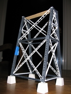
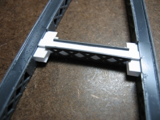
Several modifications are needed to the stock ME bents to obtain an appearance closer to GN practice. You will need an extra ME kit to provide additional material to accomplish the modifications. The first change is to add an additional cross brace to the “second story” of the bent. I constructed the brace from styrene strip and pieces of lattice strip from the ME kit. Custom cross braces also had to be be built for bents that were shortened to match the planned coulee terrain. Likewise if bents had different heights in the tower, custom braces were built in a similar manner. I basically used the same technique of building the custom brace from styrene stock and applying bits and pieces of the lattice bracing.
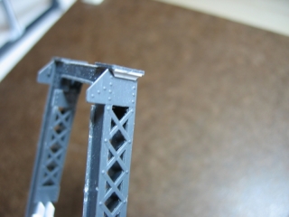
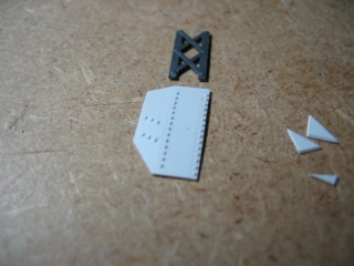
A simple modification to the bent top rivet plates to match GN practice was achieved buy simply trimming the square plate into an angle.
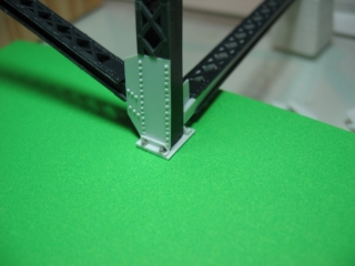
There were two additional improvements made to the model adding a small amount of detail to the top and bottom of the bents. Small pieces of styrene angle stock and nut bolt washer (NBW) castings were added to the bottom to simulate mounting bolts.
Plates & Rivets
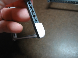
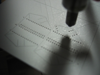
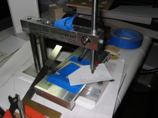
Custom rivet plates were needed in several areas to accommodate the odd angles introduced by the different bent heights. I used the CAD drawing to create the rivet plate shape (from the drawing above) and used ink jet printer to transfer the plan to the sheet styrene. A NWSL Riveter to create the “rivets” but embossing dimples in the plastic. Make sure to emboss the plastic before cutting out the smaller pieces.
Tower Assembly
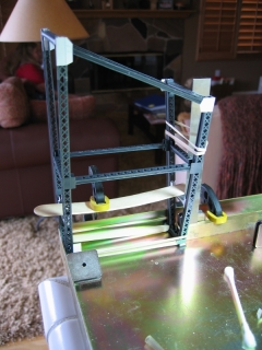
Bent assembly is probably the trickiest part of the ME kit assembly. I found a key tool to help in this process is a magnetic gluing jig from Micromark. This combined with tongue depressors, rubber bands, miniature slide clamps and a machinists square helped make sure these assemblies dried as square as possible. Work slowly and allow sufficient drying time before handling. Do not add the sway braces until the towers are assembled, dried and checked for final squareness!
When the towers with the basic bracing is dry, then the sway bracing can be added. The sway bracing provides one more chance to tweak the squareness of the towers. Once in place, they work just like the real think and no further adjustment is possible.
Coal Banks Bridge Project
This is the eighth in a series on my model of the Coal Banks trestle. Below is a listing of all the installments:
- Coal Banks Trestle: Final Assembly (January 3, 2010)
- Coal Banks Trestle: Towers (January 3, 2010)
- Coal Banks Trestle: Abutments & Piers (January 2, 2010)
Next: Final Assembly

