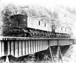
Each railroad typically develops its own way of doing things and the GN was no exception. Even within the GN, there are variations which as a modeler, we can use to our advantage when we may not have all of the details on the prototype. The Coal Banks bridge is long gone now and I only have a couple of low quality photographs to work from but by studying photos of other GN bridges, past and present, I am able to put together enough information to develop a plausible design for my model.
I built my model using the Micro Engineering trestle kits. These kits are fine models on on their own but the prototype they were based on does not match some very visible details of a typical GN design. This article highlights the differences between the Micro Engineering kit and key GN characteristics I thought were most important and visible. I adapted the kits in my model to address most of these changes. It won’t win an NMRA contest but hopefully a Goat savvy observer will recognize the model definitely as GN.
Span Girders
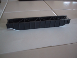
One of the most obvious characteristic present on most GN steel trestle bridges is the tapering of the span girder to match the reduced height of the tower span. The photos I have of the Coal Banks bridge indicates that this bridge also followed this design. In the Girder Span section of this article you can see how I milled the Micro Engineering girders to follow the GN practice.
Ladder Style Sway Bracing
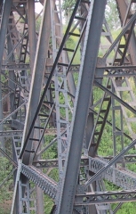
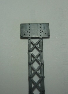
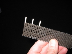
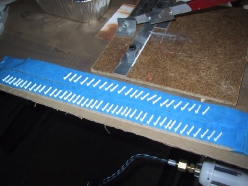
The sway braces on a steel trestle give the structure that intricate and lacey look. The stock ME sway braces model a lattice cross style. The GN used a simpler design I have dubbed a “ladder” style sway brace. The sway braces are formed by long angle iron with simple strips running perpendicular. These strips are riveted on or welded in later retrofits. This element of the modifications turned out to be the most tedious (over 750 parts) but one of the most important modifications to bring the GN look and feel. The Sway Bracing article details the techniques used to build this part of the model.
Additional Trestle Bracing
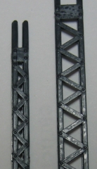
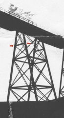
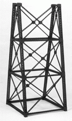
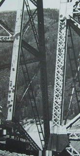
The GN tower on the left have an extra set of braces on the bents. (red arrows) The ME stock towers have three “stories” with equal bracing all around.
The standard Micro Engineering towers have three “stories” of bracing on all sides. GN Practice included an additional level of bracing on the bents themselves. It took me a while to even recognize this difference, but it adds the appearance of additional sturdiness which is of course probably why the GN followed the practice. In the Bent Assembly section, you will see the details of how I modified the stock bents to add this additional level. This modification also forces customization of the sway bracing.
Deck Walkway & Railing
The Micro Engineering bridge is designed to work with ME bridge track but I elected to use Walther’s as it comes with the guardrails molded in place. Either way, neither product addresses the wood walkways needed to match the prototype. The Deck & Railing section details how I added this feature to the model.
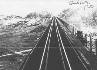
One of the photos I do have of the Coal Banks bridge is show the use of open decking and a wood walkway with railing on one side of the bridge. This was pretty standard design from the other GN bridges I have seen in photos. Thanks to Chuck Hatler for this photo of the Coal Banks bridge. Notice the wood walkway and steel railings and posts.
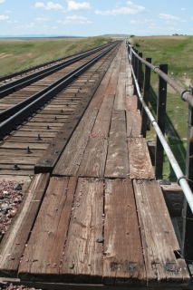
The North Fork Portage Coulee trestle, a few miles westbound of Fort Benton, MT, photographed here in 2009, provides a closeup of how the walkway and railings probably were constructed.
Trimmed Tower Top Gusset Plates
This is minor detail but it is an easy one to fix too. The gusset plat at the top of the trestle tower, used to secure the bent to bent sway braces, is square on the Micro Engineering kit. The standard GN practice appeared to trim this plate to match the angle of the sway brace. The fix was to just trim the plate prior to assembly.
Solid Plate Bents
The Micro Engineering kit bents flank the inside and outside planes of the bents with very nicely cast cross lattice. The GN did construct bridges (as in the accompanying example) in this manner but most of my photo research indicates a solid plate on the outside edge was more common. I have a theory that when many GN bridges were constructed in the earlier part of the century, the lattice bracing was sufficient. As loads increases, many GN bridges were strengthened to handle the heavier loads and used the solid plate. Fortunately, (so I can sleep at night) I do not have a good enough photo of the Coal Banks bridge to know if it had solid or open lattice bent so I elected to stay with the stock ME design. If one wanted a solid plate, the basic modification would be simple enough except for the thousands of rivets needed.
Horizontal Tower Braces
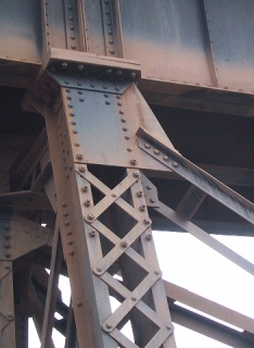
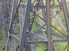
The horizontal braces on this bridge outside of Glacier Park are constructed of cross-braced horizontal beams. The ME model is cross-braced only on one side.
The horizontal tower braces on typical GN prototypes are constructed of a cross-braced lattice. The ME braces are cross-braced on the top and bottom but not the sides. I could not think of a reasonable way to construct more prototypical assembly so on this one I gave up and stuck with the stock kit. I think the impact to the model is minor.
Reinforcement Retrofits
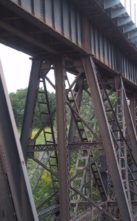
This bridge just outside of East Glacier, MT has a mix of open lattice bents, reinforced bents, and added center bent girders and girder spans.
Another example of GN bridge building practice probably related to strengthening was to add an additional center vertical girder to the bridge bents and girder spans. This would require additional trestle kits and girder spans from ME but could easily be models with the kit components. The Coal Banks bridge did not have this modification, probably because this was not the preferred line to Great Falls and therefore did not see as much heavy traffic but I include it here to close on my analysis of GN trestle bridge practices.
Coal Banks Bridge Project
This is the second in a series on my model of the Coal Banks trestle. Below is a listing of all the installments:
- Coal Banks Trestle: Decks & Railings (January 3, 2010)
- Coal Banks Trestle: Girder Spans (January 3, 2010)
- Coal Banks Trestle: Benchwork (January 2, 2010)
- Coal Banks Trestle: GN Design Practices (December 26, 2009)
- Coal Banks Trestle: Introduction (December 25, 2009)
Next: Abutments & Piers
